Gasmonitor 1-16 channel control system
General Details
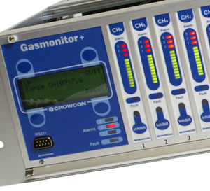
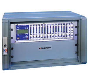
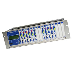
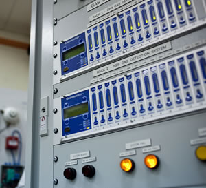
Gasmonitor Plus is Crowcon’s flexible 19″ rack-based control system. This microprocessor-controlled unit is used throughout the world, both onshore and offshore. Gasmonitor Plus can monitor up to 16 gas detectors or 32 fire zones per rack. Racks can be supplied separately, or built into wall mounting or floor standing enclosures.
A separate gas level display is provided for each gas detector. Gasmonitor Plus can be engineered into very large systems and tailored to suit individual site requirements.
Features
Simple to use
- All day-to-day functions are available from the front panel – push buttons for simple operation
- Unique bar-graph display per channel – provides instant representation of gas concentrations
- Common alarm LEDs on the display card – the whole rack status can be checked at a glance.
Flexible architecture
- System is limitlessly expandable
- Modular construction – ultimate customisation and minimal wiring
- Industry-standard analogue outputs – will integrate fully with existing rack-mounted protection systems on-site
- Optional relay modules – flexible and cuts down on configuration and monitoring cabling
Easy maintenance
- Each channel is inhibited separately – plant safety is not compromised during checks
- Routine calibration from front panel – reduces service overheads by half
- One universal gas card – reduces spares holding
Specification
| Size | 483 x 133 x 294 mm (19.0 x 5.25 x 11.5 ins) |
| Weight | 9.5 kg (21 lbs) |
| Enclosure material | Aluminium alloy |
| Mounting | Rack mounted (3u format). Wall mounted and floor standing cabinets are optional, dimensions on request. |
| Channels | 16 per rack |
| Operating temperature | 0°C to +50°C (32°F to +122°F) |
| Humidity | 0-95% non-condensing |
| Inputs | Gas 2 or 3 wire 4-20mA (sink or source), or mV bridge |
| Fire – smoke & heat detectors, manual call-points Maximum of 32 loopes per rack (ie 16 twin zone fire modules) | |
| Outputs | Analogue 16 x 4-20mA, max. load 960 Ohms or 1-5 V, min. load 100 Ohms |
| External audible/visual alarm drive Powered 24 V dc, max load up to 200mA for each alarm level. | |
| Relays | Type Up to 84 DPCO contacts rated 5 A @ 250 V ac, non-inductive load |
| Assignment – Common Alarm 1, Alarm 2, Alarm 3, Fault – Per channel Gas alarms 1, 2 & 3, fire & fault – Voting Up to 16, configurable – Relay modes Energised/de-energised, latched/non-latched, time-delayed, pulsed |
|
| Digital communications | DCS/PLC/PC/Local configuration link: RS-232 |
| Event logging | Built-in datalogger – data available via communication links |
| Panel indication | Channel number: 4 lines x 20 characters back-lit LCD display Gas reading: as above plus green LED bar-graph Measurement units: % LEL, ppm, % Vol, Fire System fault – integrity watchdog: Yellow LED |
| Alarm indication | Visual – Alarm: 3 individual & 3 common alarms (red LED); Fault – individual & common fault (yellow LED); Inhibit – individual inhibit (yellow LED) |
| Power | AC mains: 100 – 260 V ac 50/60 Hz external DC: 27.6 V Battery back-up: external |
| Approvals | Low voltage directive – EN61010-1 RF immunity – EN 50082-1 RF emissions – EN 50081-1 |